Studying a multi-axis milling CNC (Computer Numerical Control) program can be a daunting task, especially if you’re new to the field. However, with the right approach and a bit of patience, you can master this complex but rewarding skill. In this article, I’ll share my journey and the steps I took to understand and effectively use multi-axis milling CNC programs. Whether you’re a seasoned professional or just starting out, I hope my insights will help you on your path to becoming proficient in this area.
Understanding the Basics
Before diving into the specifics of multi-axis milling CNC programs, it’s crucial to have a solid foundation in the basics of CNC machining. Here are a few key concepts you should be familiar with:
1. CNC Machining Overview
CNC machining is a process used in manufacturing to control the movement of machinery and tools through computer programming. This automation allows for precise and consistent production of parts.
2. Types of CNC Machines
- 3-Axis CNC Machines: These machines can move in three directions (X, Y, and Z) and are commonly used for simple milling and drilling operations.
- 4-Axis CNC Machines: In addition to the X, Y, and Z axes, these machines can rotate around the X-axis (A-axis), allowing for more complex operations.
- 5-Axis CNC Machines: These machines can move in five directions, including rotation around the X and Y axes (A and B axes), making them ideal for intricate and detailed work.
3. G-Code and M-Code
- G-Code: This is the programming language used to control the movement of CNC machines. It includes commands for positioning, cutting, and other operations.
- M-Code: These are auxiliary commands that control machine functions like coolant flow, spindle speed, and tool changes.
Deciphering the Code: My Step-by-Step Approach
Okay, so you have a multi-axis CNC program staring back at you. Where do you begin? Here’s my tried-and-true method:
-
Start with the Fundamentals: The Header and Tool List
The first section of any CNC program usually contains the header and tool list. This is your roadmap! The header typically includes information such as:
- Program name and number
- Date of creation or modification
- Machine being used
- Material being machined
- Any specific notes or instructions
The tool list is equally crucial. It tells you:
- The tool number (e.g., T1, T2)
- The tool description (e.g., “1/2″ End Mill,” “Drill”)
- The tool diameter and length
- Spindle speed (S) and feed rate (F) settings associated with that tool
- Coolant commands (M08 for coolant on, M09 for coolant off)
Understanding this section helps you visualize the tools being used and the overall machining strategy.
-
Identify the Coordinate System:
Multi-axis machines use various coordinate systems (G54, G55, etc.) to define the workpiece’s position. Find the line of code that establishes the active coordinate system. This is critical because all subsequent movements are referenced to this origin. Make a note of the coordinate system being used; it will be vital when you are simulating the program or setting up the machine.
-
Break It Down into Blocks:
CNC programs are composed of blocks of code. Each block typically represents a single instruction or a small sequence of instructions. Don’t try to understand the entire program at once! Focus on one block at a time.
-
Focus on the G-Codes:
G-codes are the heart of any CNC program. They instruct the machine on what to do – move in a straight line, move in a circle, dwell, etc. Some of the common G-codes you’ll encounter in multi-axis programs include:
- G00: Rapid traverse (used for moving the tool quickly between cutting operations).
- G01: Linear interpolation (used for cutting in a straight line at a specified feed rate).
- G02/G03: Circular interpolation (used for cutting arcs and circles).
- G90/G91: Absolute/Incremental programming (determines how coordinates are interpreted).
- G41/G42: Cutter compensation (adjusts the toolpath to account for the cutter’s radius).
- G43: Tool length compensation (applies the tool length offset).
- G54-G59: Work coordinate systems.
Write down each G-code and its associated parameters (X, Y, Z, A, B, C, F, S). What is the machine being commanded to do?
-
Pay Attention to A, B, and C Axes:
This is where multi-axis programming gets interesting! These axes control the rotation of the tool or the workpiece. Understanding how these axes are being used is crucial. Are they being used for positioning only, or are they being interpolated simultaneously with the linear axes during cutting?
- Positive values usually indicate clockwise rotation.
- Negative values usually indicate counter-clockwise rotation.
-
Visualize the Toolpath (Simulation is Key!)
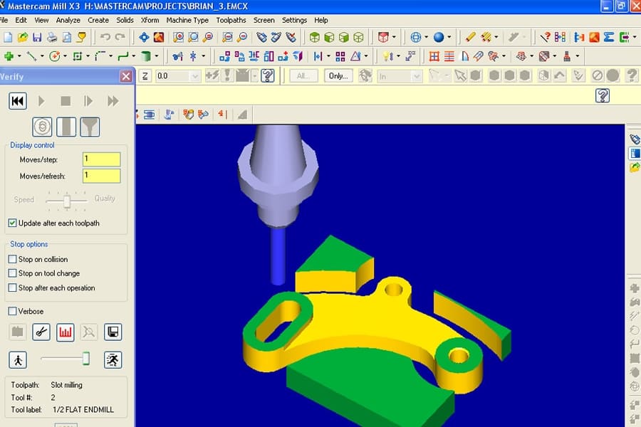
One of the most helpful things I’ve learned is the power of simulation software. There are several excellent CNC simulation programs that allow you to virtually run the program and visualize the toolpath. This allows you to identify potential collisions, verify the machining strategy, and gain a deeper understanding of the program’s logic. I highly recommend investing in a good simulator!
-
Document Everything!
As you work through the program, document everything. Create a spreadsheet or a notebook where you can record the purpose of each section of code, the function of each G-code, and any observations you make about the toolpath. This documentation will be invaluable when you need to troubleshoot problems or modify the program in the future.
Getting Started with Multi-Axis Milling CNC Programs
1. Choose the Right Software
To study multi-axis milling CNC programs, you’ll need a powerful and user-friendly CAD/CAM (Computer-Aided Design/Computer-Aided Manufacturing) software. Some popular options include:
- SolidWorks
- Fusion 360
- MasterCAM
- NX (Siemens)
2. Familiarize Yourself with the Interface
Spend some time exploring the software’s interface. Understand where to find the tools and commands you’ll need. Most software programs have tutorials and user guides to help you get started.
3. Practice with Simple Projects
Before tackling complex multi-axis projects, practice with simpler 3-axis milling tasks. This will help you build confidence and develop a deeper understanding of the process.
Advanced Techniques for Multi-Axis Milling
1. Toolpath Strategies
Multi-axis milling involves more complex toolpaths to achieve the desired results. Here are some common strategies:
- Helical Milling: This involves cutting in a helical path, which is useful for deep pockets and slots.
- Contour Milling: This technique is used to follow the contours of a part, often used in mold making and aerospace applications.
- Z-Level Milling: This involves cutting at different Z levels to create a stepped or layered effect.
2. Simulation and Verification
Before running a multi-axis milling program on a real machine, it’s crucial to simulate and verify the toolpaths. Most CAD/CAM software includes simulation tools that allow you to visualize the entire process and identify any potential issues.
3. Optimization
Optimizing your multi-axis milling program can significantly improve efficiency and reduce cycle times. Here are a few tips:
- Tool Selection: Choose the right tools for the job. Consider factors like material, depth of cut, and feed rate.
- Toolpaths: Optimize toolpaths to minimize air cutting and reduce unnecessary movements.
- Machine Settings: Fine-tune machine settings to ensure optimal performance.
What is the Applications of Multi-axis Milling?
1. Aerospace Industry
Multi-axis milling is extensively used in the aerospace industry to manufacture complex components like turbine blades and engine parts. The precision and flexibility of multi-axis machines are essential for these high-tolerance applications.
2. Medical Industry
In the medical industry, multi-axis milling is used to create intricate and precise medical devices and implants. The ability to work with a variety of materials and achieve high levels of detail is crucial.
3. Automotive Industry
Multi-axis milling is also used in the automotive industry for prototyping and manufacturing complex parts. This includes engine components, transmission parts, and body panels.
FAQs
1. What is the difference between 3-axis and 5-axis milling?
- 3-Axis Milling: This involves movement in three directions (X, Y, and Z) and is suitable for simpler parts.
- 5-Axis Milling: This involves movement in five directions, including rotation around the X and Y axes, making it ideal for complex and detailed work.
2. What are the advantages of using multi-axis milling?
- Increased Precision: Multi-axis milling allows for more precise and accurate cuts.
- Reduced Setup Time: Fewer setups are required, which can significantly reduce production time.
- Complex Geometries: Multi-axis milling can handle complex and intricate geometries that are difficult or impossible to achieve with 3-axis machines.
3. What are some common challenges when working with multi-axis milling CNC programs?
- Tool Interference: Ensuring that the tool does not interfere with the part or the machine can be challenging.
- Programming Complexity: Multi-axis programs can be more complex and require a deeper understanding of G-Code and toolpaths.
- Machine Limitations: Not all multi-axis machines are created equal, and understanding the limitations of your machine is crucial.
Conclusion
Studying a multi-axis milling CNC program is a journey that requires dedication and practice. By starting with the basics, familiarizing yourself with the software, and gradually moving to more advanced techniques, you can become proficient in this skill. Whether you’re working in the aerospace, medical, or automotive industry, the ability to program multi-axis milling CNC machines will open up a world of possibilities. So, roll up your sleeves, dive in, and start creating!
