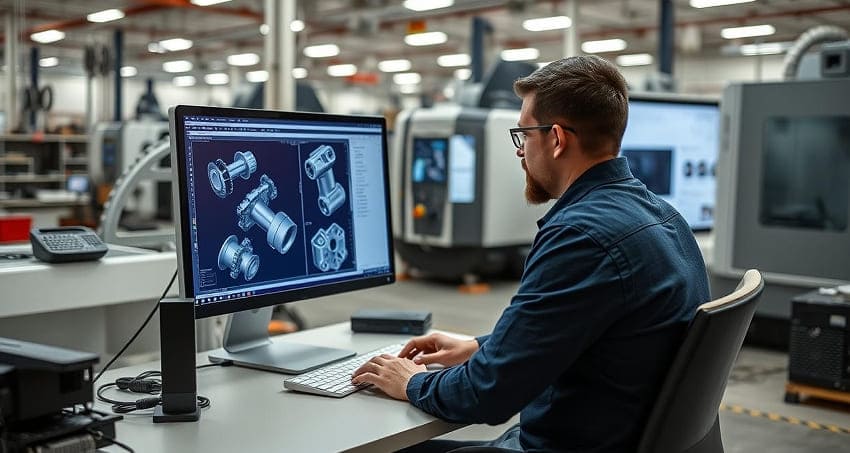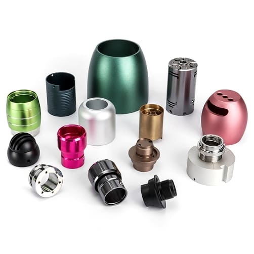
In the world of modern manufacturing, the integration of Computer-Aided Design (CAD) with Computer Numerical Control (CNC) machining has revolutionized the way products are designed and produced. As someone who has delved deep into the intricacies of these technologies, I can confidently say that understanding how CAD works with CNC machines is crucial for anyone involved in manufacturing, engineering, or product design. Let’s dive into the details and explore the synergy between these two powerful tools.
What is CAD?
Computer-Aided Design (CAD) is a software tool used by engineers, architects, and designers to create precise 2D and 3D digital models of physical objects. CAD software provides a virtual workspace where users can draw, edit, and simulate designs. These designs can range from simple 2D sketches to complex 3D models with detailed dimensions, materials, and textures.
What is CNC?
Computer Numerical Control (CNC) is a manufacturing process that uses computerized controls to operate machine tools. CNC machines can perform a variety of tasks, including cutting, drilling, milling, and turning, with high precision and repeatability. These machines are controlled by pre-programmed software, which translates the design specifications into a series of commands that guide the machine’s movements.
The Integration of CAD and CNC
1. Design Phase:
-
- Creating the Model: The process begins with the designer using CAD software to create a digital model of the part or product. This model can be as simple or complex as needed, with precise dimensions and detailed features.
- Simulation and Validation: Once the model is created, it can be simulated to ensure that it meets the required specifications. This step helps identify any potential issues or errors before the physical production begins.
2. Conversion to CNC Code:
-
- CAM Software: After the design is finalized, the CAD model is exported to Computer-Aided Manufacturing (CAM) software. CAM software is used to convert the digital design into a set of instructions that the CNC machine can understand.
- G-Code Generation: The CAM software generates G-Code, a programming language that contains the specific commands required to control the CNC machine. These commands include the tool paths, speeds, and feeds necessary to create the part.
3. Machine Setup:
-
- Tooling and Material: The CNC machine is set up with the appropriate tools and materials. This may involve installing cutting tools, setting up the workpiece, and ensuring that the machine is calibrated correctly.
- Loading the G-Code: The G-Code file is loaded into the CNC machine’s control system. The machine then reads the code and begins the manufacturing process.
4. Manufacturing Phase:
-
- Execution of Commands: The CNC machine follows the G-Code instructions to perform the required operations. This may involve moving the cutting tool along the specified paths, adjusting the speed and feed rates, and making precise cuts or movements.
- Quality Control: During and after the manufacturing process, the part is inspected to ensure that it meets the design specifications. Any deviations or issues are addressed, and the part may be reworked or scrapped if necessary.
5. Post-Processing:
-
- Finishing Touches: Once the part is manufactured, it may undergo additional finishing processes, such as sanding, polishing, or painting, to achieve the desired surface finish.
- Inspection and Testing: The final part is inspected and tested to ensure it meets all quality and performance standards.
Benefits of CAD in CNC Machining
The integration of CAD with CNC machining offers numerous benefits that enhance the efficiency, accuracy, and versatility of the manufacturing process. Here are some of the key advantages:
-
Precision and Accuracy
- Exact Dimensions: CAD software allows for precise measurements and dimensions, ensuring that the final product meets the exact specifications.
- Error Reduction: By catching design flaws early in the digital stage, CAD helps reduce errors and rework, saving time and resources.
-
Efficiency and Speed
- Faster Design Iterations: CAD software enables rapid design iterations, allowing designers to quickly test and refine their ideas.
- Streamlined Workflow: The seamless integration of CAD and CNC reduces the time between design and production, accelerating the manufacturing process.
-
Cost Savings
- Reduced Material Waste: Accurate designs minimize material waste, leading to cost savings.
- Lower Production Costs: By optimizing the design and manufacturing process, CAD and CNC can significantly reduce overall production costs.
-
Versatility and Flexibility
- Complex Designs: CAD software can handle complex geometries and intricate designs that would be difficult or impossible to create manually.
- Customization: CAD allows for easy customization of parts, making it ideal for producing unique or personalized products.
Popular CAD Software
There are several CAD software options available, each with its own set of features and capabilities. Here are some of the most popular CAD software used in CNC machining:
-
AutoCAD
- Overview: AutoCAD is one of the most widely used CAD software, known for its robust 2D and 3D design capabilities.
- Features: Layer management, 3D modeling, and advanced annotation tools.
- Industries: Architecture, engineering, and manufacturing.
-
SolidWorks
- Overview: SolidWorks is a powerful 3D CAD software that is particularly popular in the manufacturing industry.
- Features: Parametric modeling, assembly design, and simulation tools.
- Industries: Mechanical engineering, aerospace, and automotive.
-
Fusion 360
- Overview: Fusion 360 is a cloud-based CAD software that offers a comprehensive suite of tools for design, engineering, and manufacturing.
- Features: Integrated CAD, CAM, and CAE (Computer-Aided Engineering) tools.
- Industries: Product design, manufacturing, and prototyping.
-
Inventor
- Overview: Autodesk Inventor is a 3D CAD software that is part of the Autodesk suite of products.
- Features: Parametric and direct modeling, assembly design, and simulation.
- Industries: Mechanical engineering, manufacturing, and product design.
CAD File Formats
Understanding the different CAD file formats is essential for ensuring that your designs can be accurately interpreted by CNC machines. Here are some of the most common CAD file formats:
| File Format | Description | Common Use |
|---|---|---|
| .DWG | AutoCAD’s native file format. | 2D and 3D drawings. |
| .DXF | A universal file format that can be read by most CAD software. | 2D and 3D drawings. |
| .STL | A file format used for 3D printing and rapid prototyping. | 3D models. |
| .IGS | A standard file format for exchanging 3D CAD data. | 3D models. |
| .STEP | A standard file format for exchanging 3D CAD data. | 3D models. |
| .SLDPRT | SolidWorks’ native file format for parts. | 3D parts. |
| .F3D | Fusion 360’s native file format. | 3D models and assemblies. |
What Are Some Common Challenges in the CAD-to-CNC Workflow?
While the CAD-to-CNC workflow offers numerous benefits, there are also some challenges to be aware of:
-
File Conversion Issues
- Converting CAD files to a CNC-readable format can sometimes result in data loss or formatting issues. It’s important to use reliable software and carefully check the converted files to ensure they are correct.
-
Machine Setup and Calibration
- Proper setup and calibration of the CNC machine are crucial for accurate manufacturing. Any errors in this step can lead to defective parts. Regular maintenance and calibration can help mitigate this issue.
-
Material Selection and Tooling
- Choosing the right materials and cutting tools is essential for achieving the desired results. Different materials may require different tools and settings, so it’s important to have a good understanding of the material properties and the capabilities of the CNC machine.
-
Quality Control and Inspection
- Even with the precision of CAD and CNC, it’s important to inspect the manufactured parts for any defects or discrepancies. Implementing a robust quality control process can help catch and address issues early.
FAQs
-
What is the difference between CAD and CAM?
- CAD (Computer-Aided Design) is used to create digital designs, while CAM (Computer-Aided Manufacturing) is used to generate the toolpaths and instructions for CNC machines to manufacture the designs.
-
Can I use any CAD software with CNC machines?
- Most modern CNC machines can work with a variety of CAD software, but it’s important to ensure that the file formats are compatible. Common formats like .DWG, .DXF, and .STL are widely supported.
-
How do I convert a CAD file to a CNC file?
- You can use CAM software to convert CAD files into CNC files. The CAM software will generate the toolpaths and G-code, which the CNC machine can then interpret and execute.
-
What are some common issues when using CAD with CNC?
- Common issues include file format incompatibility, incorrect units, and design flaws that can cause errors during the machining process. Regularly checking and validating your designs can help prevent these issues.
Conclusion
The integration of CAD with CNC machining has transformed the manufacturing industry, offering unparalleled precision, efficiency, and flexibility. By understanding how CAD works with CNC machines, you can harness the full potential of these technologies to create high-quality products and streamline your manufacturing processes. Whether you’re a designer, engineer, or manufacturer, the synergy between CAD and CNC is a powerful tool in your arsenal.
By exploring these resources and continuing to refine your skills, you can become a master of CAD and CNC machining, opening up endless possibilities for innovation and creativity.
Additional Resources
- AutoCAD Tutorials: Autodesk Learning
- SolidWorks Training: SolidWorks Learning Center
